The rear brakes on road CSR's are to big to fit inside 13" rims, which makes the availability of tyres a bit limited. Most suitable slicks are 13" and if your're looking for second hand, 15" slicks are like water in the dessert. (see my previous
email conversation with Avon)
I recently found myself a source for
second hand Radical slicks at a very good price, so I decided to do whatever it takes to make 13" rims fit my car.
I ordered these nice looking split rims from Simon at
7tips, who were very helpful.
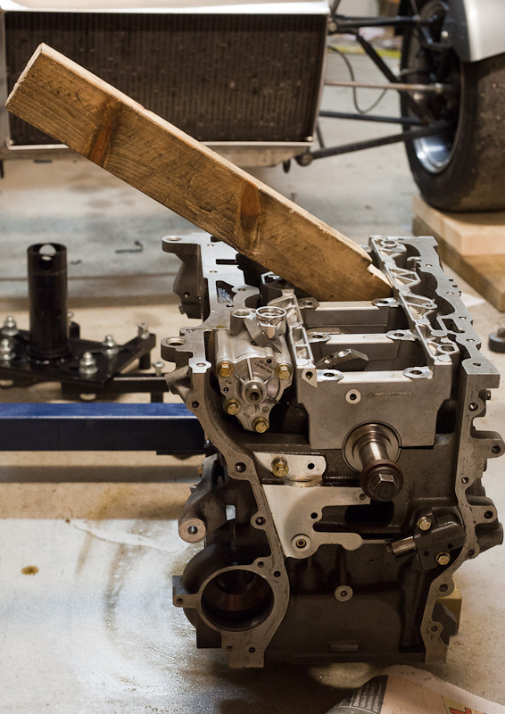
After a bit of grinding on the caliper cooling fins the rims fitted with 1.5-2mm clearance. The most grinding was on the inside part of the fins. It was an easy job to grind the calipers. Put the car on axle stands and start grinding. Measure caliper clearance by crawling under the car and measure from the inside with a feeler gauge.
 |
| Before |
 |
| After |
Unfortunately the hydraulic brake hose connector just barely touched the inside rim edge, so I had to either modify the connector, or put a thin spacer plate on the wheel hub.
 |
| Brake hose connector touching. Photo from the inside |
Since I was concerned the wider tyres might touch the rear fenders I decided to use a banjo fitting to the calipers instead of spacers. After lots of searching for a what I thought would be a suitable banjo adapter I ended up ordering new brake lines with pressed banjo fittings. Unfortunately there was a misunderstanding with the supplier (who also was very helpful), but to keep a long story short I bent the banjo fittings myself. No problems, and the end result was good, but this can probably be done in a more clever way. It might not be necessary to have new hoses made up if you put some more effort into this. I also had to grind a small edge to make the banjo fit the caliper.
Rims
7" x 13" et40 - 139mm backspace
9" x 13" et30 - 158mm backspace
Simon at 7tips said my requested backspace on the rears was between sizes, so the backspace I got differs some than the CSR rims from Caterham (but I haven't checked how much). Be careful not to have too little backspace or the wheels will foul the rear fenders. With about 1.5 degrees of neg camber I have just about 5 millimetres to spare with my wide Dunlop slicks.
Weight
I compared the weight between my 13" 7tips wheels and 15" Caterham.
15" Caterham rims with very worn ACB10: 11.3 kg front, 14.3 kg rear
13" split-rims with wider Dunlop slicks: 9.0 kg front, 10.6 kg rear
That is a difference of 12 kg rotating inertia mass total! Using
this spreadsheet that would estimate around 70kg lower chassis weight.
New brake lines (instead of spacers):
Banjo 12mm (long version)
Hose connector straight 3/8-24 conc female
Hose length 60cm (minimum, plus connectors)
Banjo bolt M12x1mm
Washers (two per caliper)
I ordered mine from
NBM Hydraulic
The standard brake lines are 3/8-24 in both ends.
Spacer plates (instead of banjo fittings)
PCD 4-108 63,3mm M12 Ford standard.
 |
| They sure look fast! |
Disclaimer
Beware, this is on your own risk! I have no idea how this affects caliper strength or heat transportation. I also don't know how much the calipers flex when braking hard, and
I still haven't test driven this. But from my limited knowledge I don't think this will affect strength much.
If you believe it was too much grinding,
MOG Racing sells a kit which also includes modified brake hose connectors.
UPDATE: Now
I have tested them on track.
See also
Trackday slicks part #1,
Trackday slicks part #2 and
Trackdays slicks part #4


