Showing posts with label Engine rebuild. Show all posts

2016-12-09

DIY Duratec balance shaft delete

Some Duratec blocks are equipped with a balance shaft. As most sports car owners are more concerned with weight and rotary mass than ride comfort that is something that needs to be removed. A balance shaft are a quite big lump of iron situated below the crank, inside the sump, and a dry sump doesn't have room for it anyway.

Plug before punched in place.
The only problem is that there is an oil supply to the balance shaft that needs to be blocked. You can find kits for that from Cosworth among others. They're not expensive but as usual Cosworth's delivery times are not from this earth so I decided to try a DIY solution.

A M8 cap head bolt and some grinding made a perfect fit. Degreased with acetone and then Loctite cylindrical bonding. Unlike my VCT Delete stub this plug does take load from the oil pressure. Therefore I filed the plug on the cap head side, making the hole a bit deeper than the plug. Then I carefully deformed the block with a punch so the plug would be kept in place.

2016-11-26

VCT Delete


Using aftermarket cams on a VCT Duratec head requires that the VCT valve is removed. Unfortunately this opens up an oil passage which must be blanked, and doing so without eliminating the oil supply to the no 1 cam journal.

This is also known as "VCT Delete", and hardware for this can be bought from massivespeedsystem.com in the USA.

But importing stuff from the USA is not very cheap after adding postage, VAT and customs, so here is a sketch for a DIY solution.

I went to a local mechanic in the neighbourhood and got this part manufactured in aluminium.

Glued it in place using Loctite for cylindrical bonding. It won't take any load, in fact the oil pressure will generate forces in both directions and keep it in place by itself. But just to be sure, I made a punch mark that definitely will keep it in place.

2013-06-26

Cranks and rpm limit

A Duratec 2.3 engine can safely be revved up to 7200 rpm with the standard valve springs. With uprated springs it the limiting factor is the crank and according to Cosworth it can be revved up to 7700 rpm with the standard crank. Above that, a very expensive steel crank is needed. (source)

Balanced crank and front pulley
Among other places, a thread on Pistonheads several people writes that the standard crank may be up for more than 7700 rpm. On my engine the power curve was still climbing when I hit the rev limiter and I would probably gain some top end power if I could raise the RPM limit to say 8000.

What kills a crank is not power or torque, it is RPM. The force on the crank is exponential to the rpm. (source missing) That's why forced induction engines can have very much power and still use the standard crank, as long the rpm limit is kept down. Apparently the forces are specially high during downshifting.

I wrote an email to a Ford Focus engine builder and asked about their view on the subject.

"For us we have a race car and we redlined it at 8500 with no problems ever. But the engine was balanced and we even balanced it with the flywheel and clutch to make sure it was perfect! It can be done but just take all precautions needed..."

I did a simulation in Optimum Lap and a 8000 rev limit would do about 0.5 seconds on Mantorp. Not much and I'm doubtful it is worth the extra risk and engine wear, but as my engine is in pieces I went to a engine workshop anyway to have my crank, pulley, flywheel and clutch balanced. It doesn't cost much and it would decrease the loads on the bearings even if I increase the rev limit or not. I also hope it would reduce some vibrations at high rpm making it easier to stay focused on the race track.

Balanced clutch and flywheel
The mechanic explained they put the crank in their machine and start rotating the crank and measuring the imbalance. After some adjustments by removing metal the balance "was zero" and he put on the flywheel and balanced again. Then the clutch and finally the front pulley. That way individual components can be replaced without the need to rebalance the crank. On V engines the weight of the crank counterweights depend on the weight of the rod and piston. That is not true for inline-4 engines as there is always the same weight going the opposite direction. (as long as the piston/rod assemblies are of equal weights, which they normally are if bought as a set)

More very informative reading about cranks here.


2013-01-16

Oil catch tank

After my engine rebuild I changed the oil system to an open system and needed a catch tank. Until now I've been using a temporary solution which in every way was not very good.

FIA regulations stipulates that engines larger than 2000cc must have 3l catch tank. I'm not competing, but while I'm at it there are no reasons not to conform to regulations.

For some reason catch tanks with 3l capacity are not very common, and those that would fit under the bonnet are even less so. I ended up having one custom made. The price was about the same as buying an existing design from eBay plus vat.


I sent a sketch to Mulberry Fabrications - Mulfab and not much later I had it in my hand. It is very light, only 763g including filter.


The catch tank is fastened using rivnuts. Some day I'll replace the hoses to something more flexible as they're a bit bulky as it is now.


2012-12-18

Dry sump blanking cap

New vs old
On the EU4 CSR 200 there is a hose between the external dry sump oil tank and the dry sump. When I rebuilt my engine I changed to an open oil system, and that hose was no longer needed and the unused hole in the sump needed to be blanked.

The problem is that it uses a very unconventional thread: MF22x2.0

After many failed attempts to find a fitting blanking cap I finally went directly to the source - Titan Motorsport, and of course they had one.

So for the record, the part number is:  A1016510200A3


For both theirs and my convenience I ordered it from Burton, who in turn got it from Titan.


2012-04-06

Engine upgrade - part #9 - final results


So far the engine have behaved extremely well and almost no problems at all. A bad battery connector, small coolant leak because of a loose jubilee clip, oil filler cap leak, but nothing serious.

Then it was time for a rolling road session at Turbocenter. It was kind of the ultimate test to see if the build was successful or if the engine would dissolve in a puff of smoke. The first time Claus took it to rev limiter my hands were shaking and my heart was up my mouth, but it held together!


As you can see in the video, in the beginning there was some problems with tyre slip against the rollers. I left the car with them for a week while going for a well needed vacation and I'm not sure how he solved the tire slip, but I think he tied down the roll cage to the floor. 


The final result is: 231 hp on the rear wheels @7500 rpm. Max torque ~230Nm. It would for sure be interesting to know how much that power would equal on the flywheel, but that is impossible to find out. Google it and you'll find lots of opinions on this subject. The loss is dependant on gearing, tyre wear, tyre air pressure, moon phase etc etc and even compare the same car on the same dyno two different days could generate different results. But I guess crank power around 270-280 hp is within reason.

As seen on the chart I have a problem maintaining constant fuel pressure when power increases. The reason for this could be many, leaking low quality fuel regulator, insufficient fuel pump, clogged fuel filter, too narrow fuel lines. Before buying a new pump Claus recommended me to move the fuel regulator to the end of the fuel rail, and put the fuel return line from there. He had a neat solution for this and I might give that a go further on.

I also have a power plateau around 4500 rpm. I don't know why. Could it be the exhaust system? I leave it as it is for a while and let all this digest until I feel ready to handle it.

Immediately when I got the car I took it on a test drive. It is early April and the roads are cold and my tyres have almost no rubber at all, but on all of the first four gears I got wheel spin when getting into the engine's power band!! This is crazy!

UPDATE: A test run this morning. Here is a 110-190 km/h comparison before and after:


Special thanks to:

Hanns Per Kober
Jeremy at Cosworth
Steve at SBD Motorsport
Claus at Turbocenter
Jan at ENEM

Also thanks to:
Kenneth at Motortjänst
Nacka Biltrim
Helpful members at Focaljet


All parts:
Engine upgrade part #1 - intro
Engine upgrade part #2 - disassemble
Engine upgrade part #3 - parts
Engine upgrade part #4 - block assembly
Engine upgrade part #5 - head
Engine upgrade part #6 - putting it together
Engine upgrade part #7 - electrical and fuel
Engine upgrade part #8 - first start
Engine upgrade part #9 - final results


2012-03-12

Engine upgrade - part #8 - first start!!!

Finally it was time for the first start of the engine. The whole family was excited and my wife would help me with operating the throttle pedal, and my kids have promised not to destroy anything and keep out of the way.


  • I primed the oil system by cranking the engine without plugs. I expected a oil pressure reading on the gauge but nothing happened. I plugged a volt meter directly to the sender connector, and after a few revolutions I got a reading on the meter, so the reason I didn't see anything before was simply something with the wiring to the oil pressure gauge. Update: It was simply the oil gauge connector on the backside of the dashboard that had fell out.
  • Fuel in the tank and connected the fuel pump power. A few on/off with the ignition primed the fuel system.
  • Computer connected to ECU, extra starter battery, voltmeter connected, wife in drivers seat, kids out of the way, cameras on and... NOTHING! The starter didn't have enough power to turn the engine! Talk about anti climax!
  • Borrowing a starter battery from the daily driver and exchanging the small lightweight racing battery with a more powerful kind.
  • Another attempt was made and it started after just a few revolutions!

Engine upgrade - part #7 - electrical and fuel

My old Ford BlackOak ECU is locked so I needed a new after market ECU. My choice was MBE 9A4, because it already was proved to be working good with Duratecs, but mostly because that was the ECU my local engine builder workshop knew best and also sold parts for.

Duratec loom

As I wrote in a previous post I ordered the ECU and a Duratec loom from SB Motorsport. The loom was missing some 'features' that existed in my previous loom, so quite a lot of wiring was needed. Most if the wireing was made while the engine was in out of the car while waiting for parts. I took the original loom apart and reused the connectors, and removed the wires that was no longer needed. Two relays where already in the new loom, but I needed two more relays for starter solenoid and cooling fans.

  • Fan switch relay, controlled by the ECU.
  • Starter solenoid coil relay, from ignition key.
  • Ignition to ECU, from ignition key.
  • Coolant temp, oil pressure, rpm (from ECU), to the dash.
  • The lambda sensor connector was of the wrong type.
  • Throttle position sensor connector changed, and the TPS was calibrated.
  • The air box from Cosworth came with a Bosch MAP sensor with integrated air temperature sensor. It is not necessary with a MAP sensor with roller barrels, but I decided to use it anyway because that way I didn't need a barometer sensor. A few more electric wires from the ECU was needed, and calibration of both temp and MAP sensor. The temp sensor was calibrated using a fridge and an oven. The map sensor is linear so it was easy to calibrate once I figured out the sensor high and low spec values.
  • A new coolant sensor was fitted to the coolant elbow in the rear of the engine. I had to manufacture an adapter from a 3/8" NPT to M12x1.5 using pipe parts from the local hardware store.
  • The fuel pump controller module which exists on the EU4 model was removed, and a new adjustable fuel regulator was fitted.


  • I did a rough adjustment of the fuel regulator using an electric tyre air pump with manometer. Cosworth recommends 4.3 bar for their 280 crate engine.

Next part: Engine upgrade part #8 - First start


All parts:
Engine upgrade part #1 - intro
Engine upgrade part #2 - disassemble
Engine upgrade part #3 - parts
Engine upgrade part #4 - block assembly
Engine upgrade part #5 - head
Engine upgrade part #6 - putting it together
Engine upgrade part #7 - electrical and fuel
Engine upgrade part #8 - first start
Engine upgrade part #9 - final results

2012-03-07

Engine upgrade - part #6 - putting it together


  • Head and block now back together with new ARP bolts and new gasket. 60 lb/ft in three stages and ARP lube. A dab of sealant on marked spots in the assembly guide.
  • Chain guides and cam chain.
  • Alternator

  • Roller barrels
  • New fuel rail and injectors (310 g/min)
  • I put the engine on the floor and mounted the flywheel with new OEM bolts. The flywheel could be easily locked using a chisel on the starter ring, holding it against the block.
  • The old clutch. I already had the type of clutch used on CSR 260. I used an extended socket I normally use for the spark plugs as centring tool.

  • Coolant hoses and coolant rail. I made a simple coolant temp sensor adaptor (M12*1.5 to 3/8" NPT). Or actually, I let the engine builder thread the inner hole because I didn't have the right tap.
  • The old hose from the oil tank to sump was plugged using a standard brass 1/2" NPT plug from the hardware store. Here I can save a few grams by changing to an aluminium plug :-)
  • Cam chain and camshaft sprockets with new bolts and new friction washers.
  • Front cover with sealant
Finding true TDC
  • Front pulley. New bolt and new friction washer. First I put cylinder 1 on true TDC, using a dial indicator and pencil. I locked the pulley with a small bolt through the locking hole. A helper hold the flywheel using the rear part of an hammer against the starter ring and a bolt in one of the bell housing holes. With a big breaker bar I could turn the bolt the last 90 degrees. Not easy, but it worked. The cams were not locked during the tightening of the front pulley.
Locked cams
  • Then it was time for cam timing. The cams where locked using the timing bar grooves and cylinder 1 was put at true TDC again, and the cam bolts where tighten. The timing was then measured with a dial indicator by turning the engine and with a degree wheel find when the intake and exhaust valves are fully open. To my surprise the timing was spot on and no adjustments were necessary.
  • Cam cover
  • Belt, belt tensioner
  • Starter motor (35 Nm)
  • Bellhousing and gearbox (47 Nm)
  • Airbox and filter, using thread lock! I don't want any of those screws sucked into the engine.

And... the engine is finished! Time to put it back into the car.

Shoe horning the engine into the car is really frustrating. After some cursing I removed the oil cooler/filter holder and starter motor. Much easier, but maybe not that easy to put them back on.


The brake master cylinder fooled the new air box, so I had to remove some carbon from the air box.

Next part: Engine upgrade part #7 - Electrical and fuel


All parts:
Engine upgrade part #1 - intro
Engine upgrade part #2 - disassemble
Engine upgrade part #3 - parts
Engine upgrade part #4 - block assembly
Engine upgrade part #5 - head
Engine upgrade part #6 - putting it together
Engine upgrade part #7 - electrical and fuel
Engine upgrade part #8 - first start
Engine upgrade part #9 - final results

2012-03-05

Engine upgrade - part #5 - head

The head is back, ported nice and smooth, valve seats refurnished and the old valves grinded.

Refurnished valve seats
Smooth inlet
  • Fitted new valve seals. Just press them in place with a socket large enough.
  • Installed the valves with uprated Cosworth springs
Valves, springs, retainers and cotters
  • Put back the old cam followers and installed the new camshafts. 
  • Measured cam to valve clearances "lash" with feeler gauges. According to Cosworth the clearance should be inlet 0.22 – 0.28mm and exhaust 0.27 – 0.30mm for my cams. They were all off since the refurnished valve seats made the valves to sink deeper into the the valve seats. To be sure I moved around the old buckets and remeasured several times, but the readings were not that consistent, and some clearances was too small for even the smallest feeler gauge. 
  • Eventually I had a complete list of the sizes I needed with 13 new buckets. A few of the sizes was more or less guesses, so I was prepared to order a couple more later on.  Finding a retailer with the buckets in stock was not easy, but to the rescue was SBD Motorsport who had them shipped within a couple of days. Cosworth also had them in stock, but to quote someone well known in the business - "nothing is fast from Cosworth other than their engines". 
  • Meanwhile I fitted the head back to the block with new ARP studs and a new gasket. No problems but I was really close to drop a washer into an oil gallery.. Phew..
  • Doh! Measuring lash before attaching the head to the block was a bad idea. Some of the measurements have changed (and some was more or less guesses to begin with). A new order to SBD, luckily the delivery was only a couple of days.
Finding TDC using a pencil and a dial indicator
  • Buckets in place and lash within spec
  • Camshafts in place with lots of assembly lube.
Next part: Engine upgrade part #6 - Putting it together


All parts:
Engine upgrade part #1 - intro
Engine upgrade part #2 - disassemble
Engine upgrade part #3 - parts
Engine upgrade part #4 - block assembly
Engine upgrade part #5 - head
Engine upgrade part #6 - putting it together
Engine upgrade part #7 - electrical and fuel
Engine upgrade part #8 - first start
Engine upgrade part #9 - final results


2012-01-31

Engine upgrade - part #4 - block assembly

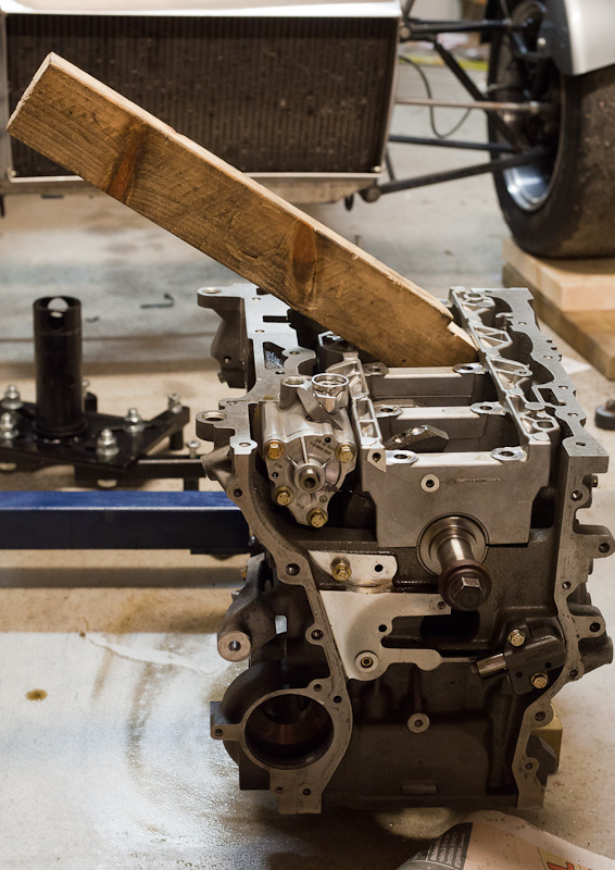
The block is back from the workshop, clean as a silver plate, and finally I could start to assemble the engine. Torques are taken from the Ford Duratec assembly manual unless other sources are mentioned.


ARP studs and main bearings
´
  • Main bearings, greased with assembly lube
  • Crankshaft
  • ARP main bolts (60 lb/ft in = 89 Nm in three equal steps with ARP lube. Source: ARP)
  • Rear oil seal (9.8 Nm)

Cover plate

  • Crank oil breather cover plate (9.8 Nm with Loctite 5910 sealant)


Measuring ring gap. The cylinders are honed by the shop.
  • Checking piston ring gap using feeler gauges. Upper compression rings needed some adjustment - I gapped them so the 0.40mm feeler just could get between with some resistance. (upper 0.25-0.51mm, lower 0.50-0.63mm. Source: Cosworth)
Carrillo recommends the following method for tighten con-rod bolts: "In order to check bolt stretch, simply fixture one rod, leaving the cap portion free from clamping load. Measure both bolt lengths loose, then progressively tighten the bolt until the measured increase in length correlates with the figures below. Use the indicated torque reading to tighten all the connecting rods in final assembly." Specified stretch is 0.130-0.160mm, max 54 Nm. Source: Carrillo.
Very simple home made bolt stretch gauge

Well, even if my stretch gauge was a bit primitive I was pretty sure I didn't reach the min-stretch value using 54 Nm of torque, even if I tighted them serveral times. After consulting Carrillo I got the response "The 40 ft lbs (=54 Nm) is the number we use to make sure that people who do not check stretch do not over torque the fasteners. If you have to go above the 40 ft lbs this is ok to do to reach the proper stretch."

I used the anti-seize lube supplied with the rods.


Pistons in place, from below

Pistons in place, from above


Then some trouble...

When I was about to mount the dry sump, it got apparent that something was wrong. The new ARP studs where a bit too long, and interfering with the bolts fasting the sump's windage plates.

The sump with windage plate and its black bolts. 
ARP stud against bolt


OEM bolt compared to ARP 


Cosworth say they use OEM bolt on their 280 crate engines, but in their catalogue they have the option to upgrade to ARP bolts. When looking at pictures on the dry sump, they looks a bit different than mine so I maybe I have an early version of the sump?

Some people I asked said the OEM main bolts could be reused. Other said never, ever, reuse TTY bolts. One or two of my old OEM bolts looked a bit stretched, and was a few tenths of mm longer than the others so I didn't dare reusing it.

I consulted ARP technical support who said that it was ok to remove some material from the studs if they're too long. They also said never to mix different materials, the washer included.

So it took the studs out from the engine again, and cut about 3 mm with a angle grinder. Much easier than I thought it would be, they cut right off. Unfortunately that was not enough as I also had to grind the windage plate bolts in the sump making their profile a bit lower. (and harder to remove in the future).

And finally I could mount the dry sump. I used Loctite 5910 sealant.


  • Oil pump chain + spockets + tensioner. New uprated friction washers on the main shaft sprocket.
  • Water pump + thermostat
  • Oil cooler and filter holder


2012-01-02

Engine upgrade - part #3 - parts

Now the larger parts of the engine are nicely packed into plastic bags for travel to the local engine workshop for a head port and cleaning.

Unfortunately I have been set on hold here because they're currently closed for Christmas holidays. Meanwhile more planning, more ordered parts and doing more research. I also took the opportunity to clean some hard to reach parts in the engine bay, as well as doing other normal winter maintenance stuff.

Rod bolt cap
So far there have been surprisingly little documentation on the Cosworth parts I've received. It feels like it have been necessary to drag out the information I needed. My questions might have been of the newbie kind, but I can't believe that Cosworth can't tell me what torque or stretch to use for the con rod bolts, or point me in the right direction of where to find that information. But after reading on the bolt caps it didn't take long to figure out where the rods came from :-) - Carrillo - who had very good documentation on their website. But why couldn't Cosworth tell me that?

Quite the opposite has Steve at SBD Motorsport been. I don't know if I even asked a question, he provided me with all information I needed right away, and then even more details I didn't know I needed. On their website they have lots of instruction sheets and drawings. I like!
Roller barrel porn

Burton Power have also been fast to reply on emails and have good reading in their catalogue and on their website. Their prices are good too!

Parts list
I've received some of the parts, some are still pending delivery.

Pocketed pistons. Big pockets on the inlet side.
Cosworth parts

  • Forged piston set 13:1
  • Forged con rod set 2.3 
  • HD Con rod bearing set
  • HD Valve spring set
  • Camshaft 250/280hk (Inlet: lift 12.5mm duration@0.050" 258, Exhaust: lift 11.3mm duration 244)
  • Fuel rail & injectors (310g min/431cc)
  • Barrel throttle bodies (45mm bore)
  • Barrel throttle filter kit (100mm trumpets)
  • Cam friction washer


Ford std parts

Unpackaging parts from Burton

  • Head gasket
  • Exhaust gasket
  • Front pulley bolt
  • Crank sprocket friction washer
  • Cam bolts
  • Flywheel bolts
  • Valve seals
  • Cam follower buckets, various sizes


ARP bolts

  • Mains stud kit
  • Head stud kit


Electrical (from SBD Motorsport)

  • MBE 9A4 ECU
  • Duratec loom
  • Bosh water temp sensor
  • Air temp extension loom
  • CAN mapping kit
  • Misc connectors + wire


Misc

  • Weber alpha adjustable fuel regulator
  • Loctite 5910 sealant
  • NGK spark plugs
  • Oil filter
  • Engine assembly lube
  • Oil catch tank (still unordered, ebay?)
  • PCV valve cover plate (found on ebay)


Tools

  • Timing disc
  • Dial gauge + stand
  • Engine stand
  • Micrometer
  • Digital torque wrench
  • Thread taps

Next part: Engine upgrade part #4 - block assembly


All parts:
Engine upgrade part #1 - intro
Engine upgrade part #2 - disassemble
Engine upgrade part #3 - parts
Engine upgrade part #4 - block assembly
Engine upgrade part #5 - head
Engine upgrade part #6 - putting it together
Engine upgrade part #7 - electrical and fuel
Engine upgrade part #8 - first start
Engine upgrade part #9 - final results


2011-12-28

Engine upgrade - part #2 - disassemble


  • Engine out
  • Bell-housing off
  • Clutch off
  • Flywheel off 
  • Mounted engine on stand using bell-housing bolt holes (M10x75 bolts. Use washers to protect the engine.)
  • Intake plenum off
  • Removed loom 
  • Fuel rail and injectors (undo nuts and pull)
  • Coils and plugs
  • Belt and tensioner

Next up was the first challenge - undo the front pulley nut using hand tools . I used a tremendous breaker bar on the pulley nut, and mounted a spanner as opposite lock on the flywheel, using one of  the old flywheel bolts. The spanner was locked against one of the engine stand mounting points. It would have been a lot easier with an impact gun. The pulley bolt shouldn't be reused.


  • Coolant rail + hoses
  • Alternator
  • Starter motor
  • Oil cooler
  • Thermostat
  • Water pump
  • PCV valve + cover
  • Cam cover
  • Front cover

  • Exhaust cam sprocket. 
  • Cam chain
  • Chain guides
  • Oil pump chain tensioner
  • Oil pump sprocket - tough one. I don't know why it was so tight on my engine. 
  • Cam/pump sprocket on main shaft - thin washer on each side.
Cam chain and oil pumps chain

  • Now finally I could remove the sump! Be careful with two bushes with five small o-rings that will fall out.
Cosworth dry sump

Note the o-rings

  • Intake cam sprocket
  • Cam caps and camshafts. Remember location and direction of cam caps.
  • Cam buckets. Remember location of each bucket. The size of the bucket is written on the inside, write down for later.

  • Head off. Torx 55 and breaker bar. But what is that really bad smell!?
Head off

  • Cotters, retainers, springs and valves. Remember location. Hint: Use a strong magnet to remove the cotters.
  • I left the valve seats in place. Hopefully they can stay there.
Removing springs
Ordning och Reda

  • Pistons - will be replaced. Torx 55. Mark them. Direction is already marked as arrows on top of the pistons.
Old pistons

  • Pistons big end bearings. These will also be replaced, but keep location and direction just in case?
  • Since I couldn't reach the crank rear seal bolts when the engine was mounted to the engine stand I took it down on the floor and put it on some pieces of wood. Now it was so light I could lift it myself. I also took the opportunity to measure crankshaft play. (0.28mm, spec is 0,22-0.43mm)

  • Rear oil seal 
  • Crank bolts. Breaker bar and oomph!
  • Crank cap. Used a piece of wood for leverage.
Crank cap


  • The crank! ~16 kg!
Crank shaft

  • Main bearings. Keep location and direction!
Main bearings

  • And... that's it! 
Now I'll take the block and head to my local engine workshop for cleaning, honing and head port.