Showing posts with label ECU. Show all posts
2013-12-23
Race Technology DL1 + Dash4Pro
Early Christmas this year when I got myself a Race Technology DL1 Club logger and Dash4Pro dash to go with it.
I've been using a Racelogic Performance box for many years but always longing for a system like this. One big reason for finally upgrading is to be able to see engine performance counters while driving. It can also show alerts when one or a combination of signals are out of range.
It can also show predictive lap time on the fly, and one side of the shift lights can be programmed to show time slip rate so you immediately can tell if a line is faster or not. It also syncs all logged data with my old GoPro camera and can play back the video inside the analysis software.
The display can be set up to display four screens with any of the parameters available. That means all CAN bus data from the ECU as well.
I intend to add a few sensors in the future, such as steering wheel angle and brake line pressure. If feeling extreme I could add wheel speed sensors and suspension movements. The throttle angle I can already get from the ECU.
Instead of using the supplied bracket I drilled two small holes in the steering wheel to mount the display. I wired the power from the windscreen wiper switch so I can turn the system on and off easily.
I'm really looking forward to try the system out this spring!
Labels:
Data acquisition,
ECU
2012-06-25
Fuel injector voltage compensation
I've noticed that the engine sound changes when the cooling fan kicks in. Not a big deal, I thought, but now I understand it is something worth a bit of attention.
Injector "dead time" is the time between pulse and fuel is delivered. What makes it a little bit complicated is that the dead time is not only voltage dependent but also fuel pressure dependent.
When the fan kicks in, or the headlights are lit, the battery voltage is dropped. The ECU have a voltage compensation map that add some time to the fuel map. If that map isn't correct the engine rpm may drop, causing the alternator to generate less current, even less fuel, and the engine could eventually stall. If we use closed loop lambda control the ECU would stable the engine within a second, but what would be written to the long term fuel map?
In my case the compensation map set up was not correct for my injectors.
The easiest way to measure injector dead time is to have the engine running and measure the lambda. Then remove the alternator control cable to drop the voltage about 2v, and see if the lambda changes. Adjust the map until the lambda reading is as before the alternator was disabled.
A more accurate way is to start the engine, remove the battery and connect a variable voltage source, and then disable the alternator and measure lambda at different voltage levels and adjust the map accordingly.
Or, you could do as I did and Google the injector's specs.
It worked.
Injector "dead time" is the time between pulse and fuel is delivered. What makes it a little bit complicated is that the dead time is not only voltage dependent but also fuel pressure dependent.
When the fan kicks in, or the headlights are lit, the battery voltage is dropped. The ECU have a voltage compensation map that add some time to the fuel map. If that map isn't correct the engine rpm may drop, causing the alternator to generate less current, even less fuel, and the engine could eventually stall. If we use closed loop lambda control the ECU would stable the engine within a second, but what would be written to the long term fuel map?
In my case the compensation map set up was not correct for my injectors.
The easiest way to measure injector dead time is to have the engine running and measure the lambda. Then remove the alternator control cable to drop the voltage about 2v, and see if the lambda changes. Adjust the map until the lambda reading is as before the alternator was disabled.
A more accurate way is to start the engine, remove the battery and connect a variable voltage source, and then disable the alternator and measure lambda at different voltage levels and adjust the map accordingly.
Or, you could do as I did and Google the injector's specs.
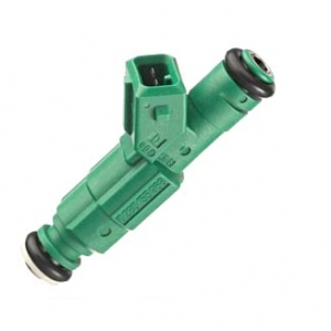
Bosch "Green giant" injectors at 4 bar, MBE 9A4:
2012-05-15
Wideband lambda
I've installed an Innovate LC-1 wideband Lambda controller connected to my MBE 9A4 ECU.
A wideband lambda output a linear 0-5V AFR (air/fuel ratio) sensor reading for a wide range of lambda values, in contrast to an ordinary lambda sensor that output more like a narrow rich/lean reading compared to a fixed reference. This makes it possible for the ECU to real time control the fuel mixture to a set value, based on the these readings - "closed loop lambda control".
The 9A4 also supports a long term AFR adjustment map, a bit like "self mapping". Some of the difference between the expected and measured lambda value is written to the long term adjustment fuel map, so the next time it is time fire the injectors for the same conditions it uses the updated value. For making the changes persistent to the primary fuel map you manually have to select to merge the long term map into the primary map with a computer connected to the ECU. The long term map is cleared after ECU power loss.
This sounds a bit too good to be true, and probably is. I've done some internet forum digging and it seems like it is not recommended to use closed loop lambda control when the engine is under high load, although the reasons why are a bit vague. For medium load and idle it seems to be no reasons not to use it. And for logging ECU data a wideband lambda sensor is a great tool.
However it won't work unless you have a pretty good base map to begin with.
The wiring was a bit fiddly and time consuming but pretty straight forward.
It took some trial and error to figure out how to program the ECU, so I thought I'd do the world a favour by showing my setup for the LC-1 controller configured with factory defaults. (Analogue 2 output from the controller into the ECU, brown wire).
Start with the "Analog Lambda Sensor 16 bit Index Map" setting. This tells the ECU the sensor input is linear and the interesting voltage range is between 0 and 5V.
Then "Analog Lambda Sensor Calibration" setting. This is what voltage corresponds to what lambda value. This is for the factory settings, 0V = lambda 0.5 and 5V = lambda 1.523.
Set the Oxygen Sensor lower and upper limits settings to 0 and 5V.
And finally you must have a target lambda map. Target lambda 1.0 at idle, and lower (richer) for more power at load.
Start the engine, and if all readings seems fine you can activate lambda control by setting "Lambda A (1) Control Enable".
After about 30 seconds from engine start, the ECU should start to adjust the engine's AFR to follow the current target lambda.
A wideband lambda output a linear 0-5V AFR (air/fuel ratio) sensor reading for a wide range of lambda values, in contrast to an ordinary lambda sensor that output more like a narrow rich/lean reading compared to a fixed reference. This makes it possible for the ECU to real time control the fuel mixture to a set value, based on the these readings - "closed loop lambda control".
The 9A4 also supports a long term AFR adjustment map, a bit like "self mapping". Some of the difference between the expected and measured lambda value is written to the long term adjustment fuel map, so the next time it is time fire the injectors for the same conditions it uses the updated value. For making the changes persistent to the primary fuel map you manually have to select to merge the long term map into the primary map with a computer connected to the ECU. The long term map is cleared after ECU power loss.
This sounds a bit too good to be true, and probably is. I've done some internet forum digging and it seems like it is not recommended to use closed loop lambda control when the engine is under high load, although the reasons why are a bit vague. For medium load and idle it seems to be no reasons not to use it. And for logging ECU data a wideband lambda sensor is a great tool.
However it won't work unless you have a pretty good base map to begin with.
The wiring was a bit fiddly and time consuming but pretty straight forward.
It took some trial and error to figure out how to program the ECU, so I thought I'd do the world a favour by showing my setup for the LC-1 controller configured with factory defaults. (Analogue 2 output from the controller into the ECU, brown wire).
Start with the "Analog Lambda Sensor 16 bit Index Map" setting. This tells the ECU the sensor input is linear and the interesting voltage range is between 0 and 5V.
Then "Analog Lambda Sensor Calibration" setting. This is what voltage corresponds to what lambda value. This is for the factory settings, 0V = lambda 0.5 and 5V = lambda 1.523.
Set the Oxygen Sensor lower and upper limits settings to 0 and 5V.
And finally you must have a target lambda map. Target lambda 1.0 at idle, and lower (richer) for more power at load.
![]() |
| Target lambda map. NOTE! The values used here are quite lean!! |
Start the engine, and if all readings seems fine you can activate lambda control by setting "Lambda A (1) Control Enable".
After about 30 seconds from engine start, the ECU should start to adjust the engine's AFR to follow the current target lambda.
2012-05-05
Air temp sender location
The Cosworth carbon air box is supplied with a combined MAP and air temp sender, which measures temp and pressure inside the air box. After studying an ECU log file it reveals its location for air temperature is far for optimal.
I have now moved the sender to in front of the left footwell. The MAP sensor I only use as a barometer sensor before starting the engine so it will do its job just as good outside of the air box.
![]() |
| Blue line is air temp. The real temperature this evening was around 11 deg C, not 29. |
I have now moved the sender to in front of the left footwell. The MAP sensor I only use as a barometer sensor before starting the engine so it will do its job just as good outside of the air box.
![]() |
| Old sensor location |
Subscribe to:
Posts (Atom)